PLC Only

Function that is used in the PLC code but does not required a HMI graphical interface.

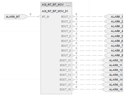
INT_TO_BIT
Integer to Bit

Integer Value Move to BIT status (Version Studio5000 V32.02)

10.00 (CAD)
Picture of Analyze_Real8_AOI
Analyze_Real8_AOI

8 input REAL value, find minimum. maximun and average. Except 0 if input value = 0, it won't be counted in sum and average

5.00 (CAD)
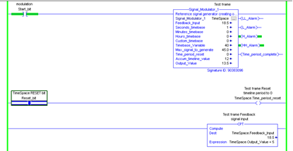
Signal generator block in ladder logic
Referance signal generator

Reference signal generator creating output value from preset during the time period.

25.00 (CAD)
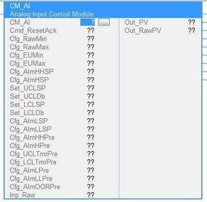
Picture of CM_AI
CM_AI

The Analog Input AOI Control Module is used to condition analog input signals into usable values for indication, control, and/or alarming by components of the PLC program or other systems (HMI, MES, etc.) Note: Programmed followed ISA88, ISA95 and ISA106 Standard

35.00 (CAD)
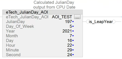
Picture of eTech_DOW_Date_AOI - ( RS/Studio5000)
eTech_DOW_Date_AOI - ( RS/Studio5000)

Studio 5000 - Rockwell Automation AOI Outputs - Julian Day, Day of Week, Is Leap Year and Current CPU Date/TIME

50.00 (CAD)
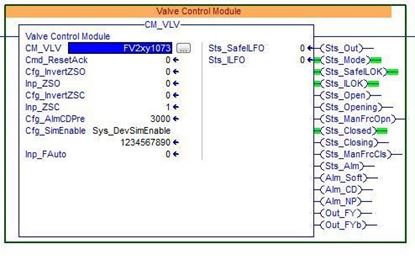
Picture of CM_VALVE
CM_VALVE

The Valve AOI Control Module can handle a spring return fail open, spring return fail close, or fail last valve. The valve can have one or two solenoids. It can have an open limit switch, or not. It can have a close limit switch, or not. Note: Programmed followed ISA88, ISA95, and ISA106 Standard
25.00 (CAD)
Picture of CM_DI
CM_DI

The Digital Input AOI Control Module is used for general-purpose discrete inputs. Note: Programmed followed ISA88, ISA95, and ISA106 Standard
15.00 (CAD)
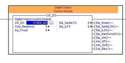
Picture of CM_DO
CM_DO

Digital Output Control Module Note: Programmed followed ISA88, ISA95, and ISA106 Standard
20.00 (CAD)
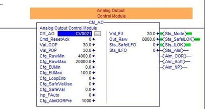
Picture of CM_AO
CM_AO

The Analog Output AOI Control Module is used to condition an engineering unit analog output value into the proper range for analog output modules and devices. Note: Programmed followed ISA88, ISA95 and ISA106 Standard

30.00 (CAD)